Two master repeaters? 🥴
Question
We have an IPSC system. We want to use a redundant setup. The main repeater IP is 100.100.100.1. The redundant repeater IP should also be given as 100.100.100.1.
In this case, a phenomenon in which conversion did not occur normally occurred (sic).
In this case, a phenomenon in which conversion did not occur normally occurred (sic).
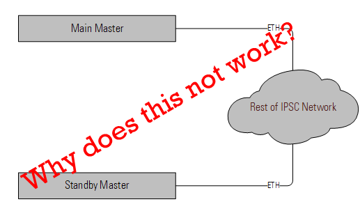
The main/standby repeaters are connected via a layer 2 network and VPN.
Looking at the information in the previous article, it says that there must be hardware equipment that can switch IP, but can you tell me the model name? Or can you give me a solution?
Answer
An IPSC system is made up of one master repeater and several peer repeaters linked via IP. In an IP backhaul network without a DNS server, the master repeater must have a static IP address. If there is no DHCP server, all the repeaters will need static IP addresses.
The master repeater is not contiguous to network operation. That is, if the master goes down for any reason, the remaining repeaters will continue to operate as an IPSC system without it. In essence, the master repeater is only needed to process repeaters joining the network (and of course to act as a repeater itself for the area it covers).
In an IPSC and Capacity Plus network, MOTOTRBO repeaters do not handle redundancy themselves. By this, I mean they do not have a built-in mechanism to hand their functionality over to another repeater when something fails. Capacity Max does however have a rollover mechanism for site controller and control channel operation.
In IPSC and Capacity Plus, it is however possible to configure two colocated repeaters to act as a redundant pair. With this configuration, a failure on the main repeater will cause the standby repeater to start working. The trouble with this setup is that it will only work with peer repeaters. If you are interested in learning about this, read this post.
In order to handle redundancy on the master repeater, one needs an external device to handle the IP-switchover between the main and standby repeater. This is necessary because when the standby repeater is disabled via the accessory connect, the parts that handle ethernet connectivity remain active. The repeaters do not support SNMP and the RDAC messaging cannot be decoded by anything other than a PC running an application.
The Latvians come to the rescue!
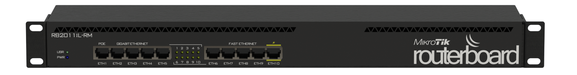
The easiest way to overcome the above is to use a router from Mikrotik and a custom script. The script basically checks the main repeater by pinging it. If there is no reply after five pings, the script makes the router load a different NAT rule then continues to ping the main repeater again.
Here, the main repeater, standby repeater and router to which both repeaters are attached, all have static IP addresses. In my example, the Router has a WAN IP of 10.0.0.1 (the routerless configuration described in this post will not work, by the way).
Since the script is untested, I've posted it to Github. You will find the latest (and debugged) version of this and other scripts here.

Repeater Configuration
Both repeaters can be configured to allow main-standby switchover via the accessory connector as shown in this post.
The main repeater would have a static IP address of (in this case) 192.168.0.2 and the standby repeater an IP address of 192.168.0.3. You can change this but remember to change the addresses in the script.
Both repeaters would use the same UDP port - this is very important.
The peer repeaters in this network would all have 10.0.0.1 as the Master Repeater IP address.
Both the main and standby repeaters can use the same Radio ID if IP Remote Programming is not used.
Everything else, not mentioned here, would be standard configuration stuff.
If anything else comes to mind, I'll add it in the comments. At the time of writing this, the script is untested so all feedback and (almost certainly) corrections are most welcome. I am no networking specialist so cavea


Leave a Comment