What is a Control Station?

A Control Station is basically a MOTOTRBO radio connected to a PC. The PC could be running some form of software that handles data and/or voice. This would be used as an alternative to using NAI and IP connectivity to the repeater(s).
If the Control Station handles data, only the programming cable is needed. If the Control Station handles both voice and data then a custom cable needs to be made, or the programming cable needs to be modified to support audio and PTT. The custom cable may also be needed if the Control Station only handles voice (sometimes called a Donor Radio) since the USB interface would be used to access display information from the radio using XCMP.
A Control Station can, in principle, either be a portable or mobile radio - however it is suggested to use a DM4_00e (a DM4_01e would be overkill, since presumably, the rack where the Control Station lives, is not moving). a DM460_e would probably be needed, if information such as Radio ID; text and prompts, normally shown on the radio display, would be needed by the host PC.

The physical interface between PC and Control Station is USB.
MOTOTRBO radio use the RNDIS protocol to create a virtual ethernet interface between the radio and PC.
When connecting to the PC, a driver is needed and installed (the driver files are included with the CPS; can be downloaded from Motorola Online or are included with the application being hosted on the PC).
Once the driver is installed, the radio will act as a DHCP server to the PC and will, by default issue an IP address in the 192.168.10.0/24 subnet. This allows applications to access the radio and radio network without having to deal with the physical interface as was the case with older radios.
In terms of being a data bearer, the radio will act as a Layer 3 device between the CAI network and ethernet (wired network).
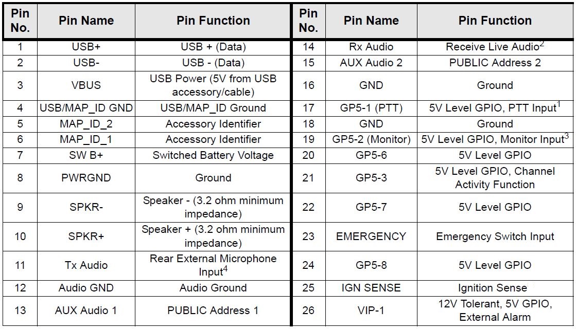
The USB interface does not pass audio so in order to access this, a custom cable is needed to link the sound card of the host PC to the radio. The LINE IN on the PC would be connected to pin 14 and the LINE OUT would be connected to pin 11. A common ground is needed and for this pin 12 should be used. Since the level from LINE OUT is much higher, some adjustment will be needed to ensure no distortion. ""Carrier Detect"" and PTT IOs arent needed since this is handled via the USB interface on pins 1-4.
 |
| This is the accessory connector pinout for the DM4000 series radio. |


Leave a Comment